 THERMAL SYSTEMS
ATLOSON PRODUCT RANGE
Find the right thermal system.
Recommended Application
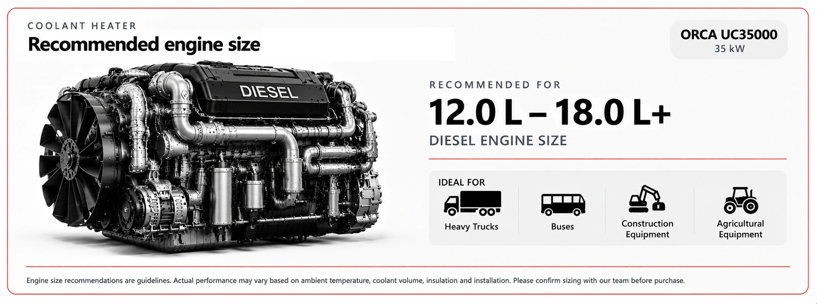
- Recommended Engine Size
- 12.0 – 18.0 L+
- Recommended Coolant Circuit Volume
- approx. 90–175 L
Recommended values are approximate and may vary depending on ambient temperature, insulation, coolant system design and application.
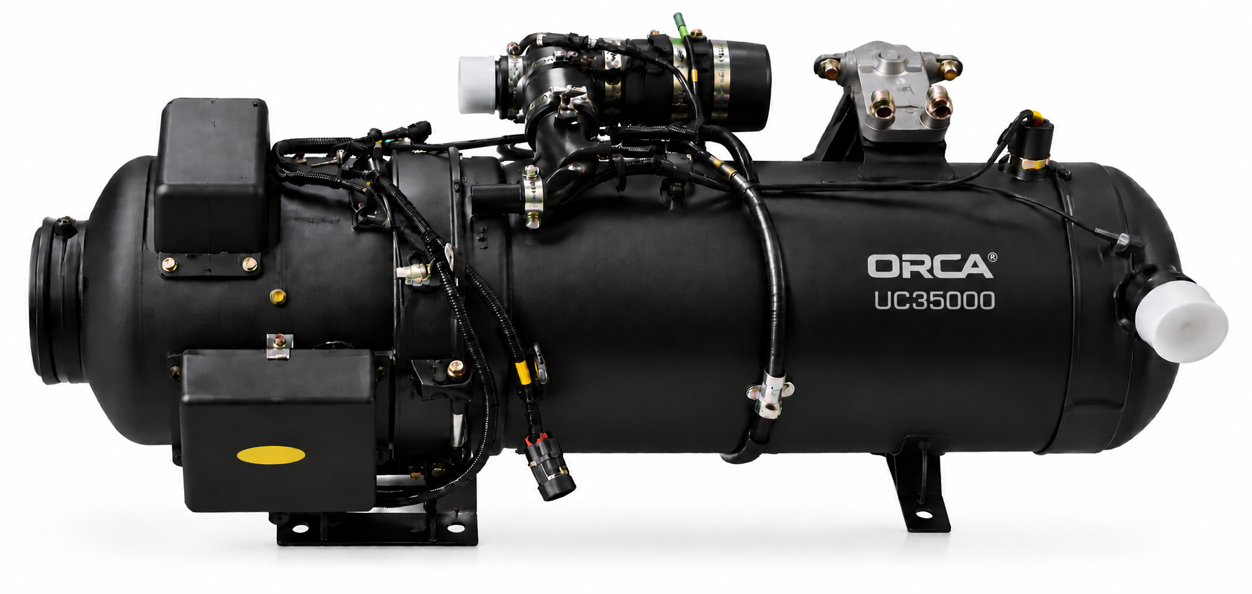
ORCA Coolant Heater
UC3500035 kW · Diesel · 12V
SKU: To confirmIn Stock
ORCA UC35000 installation & operation manual →
Select Heating Output
About the ORCA UC35000
ORCA UC35000 coolant heater, 12V configuration. Engine preheating and compatible coolant circuits. Size the system for heat demand, circuit volume and flow.
Key Benefits
- Fuel: Diesel
- Operating voltage: 12 V DC
Applications
Engine preheating and compatible coolant circuits. Size the system for heat demand, circuit volume and flow.
Complete manual downloads
- Download ORCA UC35000 Installation & Operation Manual – English PDFV5 · 6 pages · English
- Télécharger le manuel d’installation et d’utilisation ORCA UC35000 – Français PDFV5 · 6 pages · Français
- Descargar el manual de instalación y funcionamiento ORCA UC35000 – Español PDFV5 · 6 pages · Español
- ORCA UC35000 Installations- und Bedienungsanleitung herunterladen – Deutsch PDFV5 · 6 pages · Deutsch
- Скачать руководство по установке и эксплуатации ORCA UC35000 – Русский PDFV5 · 7 pages · Русский
Installation
On receipt, record the SKU, serial number, voltage, fuel and controller revision, and photograph the nameplate. Check the heater, harness, controller, pump, pipes, seals and fasteners actually supplied. Prepare maintenance access, protected routing, a suitable electrical supply and combustion exhaust outside the occupied space.
Identify coolant flow direction, high points and bleeding points. Check coolant, pump and fitting compatibility; domestic water requires a separate heat exchanger. Size the installation for the engine circuit and thermal load.
Secure the heater: Provide a rigid, accessible support. Identify coolant inlet and outlet, leaving clearance for the burner, pump and connections.
Create the hydraulic circuit: Connect to the closed antifreeze circuit. Respect flow direction and avoid restrictions and high points that trap air. Install the appropriate circulation pump and keep engine coolant separate from drinking water.
Fill and bleed: With the engine cold, fill using the vehicle-specified coolant. Open the necessary valves, bleed the heater and pump, then check level and leaks. Never start dry.
Connect combustion: Install combustion intake and exhaust outside the occupied cabin. UC5000/UC9000 use the matching metering pump. Larger units must follow the supplied burner architecture; do not substitute a small metering-pump circuit.
Check electrical supply and heating: Test supply voltage under load and coolant circulation. Measure supply and return temperatures. Check the vehicle cabin-fan control if fitted. Complete shutdown and recheck the coolant level when cold.
Commissioning checks
Check mounts, connections, protective devices and seals before starting. Bleed or prime only as instructed in the manual. Measure voltage at the appliance during startup; check stable operation, temperatures and unusual smoke or leaks. Test controlled shutdown and completion of cooling, recording conditions, measurements and serial number.
Operation
Before starting: With the system cold, check coolant level and antifreeze protection. Open necessary valves and ensure the circuit is filled and bled. Never start with an empty or frozen circuit, or open a hot pressurised circuit cap.
Engine preheating: Schedule operation only after a supervised initial test. Use the correct coolant-heater controller; displayed room temperature may not be the coolant setpoint. Check circulation, leaks and gradual temperature rise.
Cabin heating: Test any installed heat exchanger and vehicle-fan control separately. Cabin heating consumes part of the output and battery capacity; allow longer preheating than for coolant-only operation.
Shutdown or circulation fault: Stop normally using the controller, retaining power for purge and cooling. After overheating or unusually cold hoses, allow cooling and inspect coolant level, bleeding, valves, restrictions and pump before restarting.
Maintenance
Before use, check power, fuel, ducts and leaks. After moving, inspect mounts and fittings. Before the season, perform a supervised test and inspect the circuit. Allow the shutdown cycle and cooling to finish before maintenance. Follow the variant’s manual for dismantling and intervals.
Before the season, inspect mounts, wiring, pipes, outlets and protective devices; check leaks and corrosion. Clean grilles and remove obstructions without changing combustion settings. Before storage, follow water-system drainage and antifreeze procedures. After service, inspect seals and leaks, test operation and shutdown. Exact intervals depend on the variant’s manual and use.
Troubleshooting & support
Record the exact error code, a screen photograph, voltage at rest and startup, symptoms and circumstances. Check supply/connectors, fuel, intake and exhaust; on coolant systems, also check filling, bleeding and circulation. Use the installed controller’s code table; do not interchange OLED, LCD and AT1192 codes. Stop for leaks, odours or overheating and obtain professional diagnosis before replacing electronics.
Before you buy
- Required use and output
- Voltage and fuel
- Available installation space
- Combustion intake and exhaust
- Compatible controller and required installation components
- Exact packing list
Select for actual use, heat losses, climate and installation architecture. Nominal output alone does not establish compatibility or autonomy.
Size engine heating for engine mass, starting temperature, preheating target, available time and heat losses. A simple output-to-engine-displacement comparison is not a guaranteed thermal rating.
Measure the full connected circuit volume, including engine, pipes and heat exchangers. Check pump flow, pressure losses, bleeding and target temperature. For water, energy E (kWh) ≈ volume (L) × 0.001163 × temperature rise (°C); ideal time (h) ≈ E / output (kW), before accounting for losses and the engine. This estimate does not define a certified admissible circuit capacity.
Contact us about your application →Questions & answers
How do I confirm this configuration?
Contact ATLOSON to confirm the SKU, connections and delivered configuration before ordering.